Showing posts with label pca9685. Show all posts

Monday, September 9, 2013

Taking the bus (Part 3): The controller

You know the day is going to be good when the mailman rings at the door during breakfast time. Well, apart from the breakfast obviously. In my case, I was about to receive a box of fresh new and exciting components to build awesome stuff with:

Bunch of components
Among them was the ATMEGA328P microcontrollers I was eagerly waiting for to be able to build the controller module from my previous post. I already prepared the PCB (my first double-sided one, with lots of vias), meaning that I could start with all the SMD components right away:

Pilight controller board, partially assembled
After making sure that there were no shorts or dead solder joints on the board I was ready to add the headers and program the microcontroller:

Finished controller board

Port illustration
Size comparison: Full-size Arduino, Pilight controller, Arduino Mini
Programming with ArduinoISP
The programming step was a little troublesome, because I wired the cable to connect the controller to the Arduino incorrectly, meaning that my controller was missing ground and in constant reset state. Of course the cable was the last part I checked... However, after fixing it programming went fine.

After that, I hooked the board to the WS2801 LED pixel strand only to find out that i switched data & clock on the SPI port. Oh well. Luckily, I could make it work with a corresponding cable:

Controller in place
I previously named this the "Pilight universal controller" because I designed it to be able to drive all the various pilight devices - and so I needed to try the I2C port, too:

Pilight controller driving a PCA9685 PWM board
I'm very glad it all worked out so nicely. This first controller prototype will now resume its work on the pixel strand, and I am back to the drawing board to integrate the same microcontroller circuit into the LED dimmer board.

Update: Here's another short video of the controller in action. Enjoy :)


Tuesday, September 3, 2013

The new traffic light (Part 2)

UPS was so kind to deliver a batch of 20 PCA9685 chips to my door today. I was very pleased, since that allowed me to continue some of my projects. Today, I'm writing about the traffic light again, since that is the project i selected for testing.

I don't have much experience soldering SMD components, and so I immediately messed up the first board I had prepared in my previous post. Always check that your components are properly aligned with their solder pads! Moving them is pretty much impossible once a few of the pins have been soldered to the board. On a second note, I might need to get that hot air station.

I had more luck with the second attempt. Take a look at the finished board:

Top side with the two ULN2803 amplifiers

Bottom side with the PCA9685
I must admit, this is not my prettiest job. But the solder joints are all clean, and no shorts are on the board.

I had to prepare a few more cables, but once I hooked up the board to one of my Raspberry Pis it was immediately found by i2c-detect. For testing purposes I have attached a new cable to the one side of the light that I had already reworked before. I still need to get out the drill and the hot glue gun for the other three sides.

I tried it out with the Adafruit demo code that is destined for their PWM board, and since this is the exact same chip it worked right out of the box. I added a few lines and the result is a complete traffic light sequence in about 20 seconds:


But wait, there's more. I chose the PCA9685 because it is capable of outputting PWM. This is what it looks like when run with pilight code. Enjoy!


Wednesday, August 28, 2013

Getting started with Arduino

Today I came up with another nice little contraption:


Now you're probably wondering what that is. That question is pretty easy to answer: From bottom to top, that's a Raspberry Pi driving an Arduino driving a PWM board driving a 10-LED-bargraph board.

Not satisfied with this answer? I can understand that. There's more questions behind that. Let's start with the less obvious things. Why the bargraph? It's a simple component that was readily assembled and was designed to be connected to the PWM board. It's a nice visual indicator of what's going on.

Why the PWM board? Again, the answer is: because I had one at hand. I could have used something else, but in combination with the bargraph again it gives a nice visual representation of what I was trying to accomplish.

So then the real deal is in the Arduino? From my previous projects I already know that I can directly interface the PWM board from the Pi. So basically there's not a real point in passing signals through an Arduino, or is there?

Yes there is. This is the first time I'm trying to build something Arduino-related at all, and this might actually turn out to be a nice advantage to future builds.

It's the connection between the Arduino and the Raspberry Pi that I will actually try to improve upon in the next days. So all this basically is going to be my testbed with a known-working state.

Right now I'm researching ways of replacing the connection with some kind of bus (RS485 seems very promising, and from there DMX is not far away) or even make it wireless (but most solutions appear to be rather expensive). If my idea works out, this could mean that I will no longer need a dedicated Pi for each of my devices, but instead a cheaper and smaller (think of the Mini!) Arduino would be sufficient. I might event manage to integrate the microcontroller directly onto my own boards!

And now this is an answer that hopefully gives you an insight on what really lies behind a few simple lights.

Oh, almost forgot, there's also a small video. Enjoy!


The new traffic light

Well, so the 'ole traffic light I wrote about earlier has become a little obsolete recently, and so I wanted to give it a little overhaul. In my original post I already mentioned the four sides that it has, but since I was kind of lazy with the original build, only one side was actually connected. Also, since I kind of like the idea of integrating this into the PiLight system, I wanted to make the lights on it dimmable.

Since another project I'm currently working on will incorporate the PCA9685 chip, this is a good chance to try out a small part of the circuit before going large, and also makes the traffic light worthy of its own posts on this blog.

Here's a picture of the board I designed for this little project. It consists of a PCA9685, two ULN2803 amplifiers, a set of pre-resistors for the LEDs, and some more SMD passives for the configuration of the PCA.

Traffic light board design
I took some photos during the etching process for documentation. I'm working with the direct toner transfer method mainly because it's much more convenient (once you have access to a laser printer), but also because it requires less chemicals.

The first step is to cut out a piece of board that fits your dimensions.

Printed circuit on copper side (for illustration)

Marking the board dimensions on the board itself

Nice and shiny board after cutting
The next step is to transfer your design onto the actual board. This process involves a sheet of glossy paper (I just tore out a page of an old Reichelt catalogue, but from what I read most glossy magazines should do), some acetone, an iron, a bowl of soapy water and a brush.

Final board design printed onto glossy paper (had to glue it to a page of regular paper because it was too small)

Everything prepared: Iron, board, and the printout

Cleaning the board with acetone to remove any fingerprints or other kinds of dirt on the surface

Ironing the printout onto the board

This is what it looks like after ironing

Dumping the whole thing into a bowl of warm, soapy water

The paper will soak up completely in the water after a few minutes, and can then easily be brushed off.

This is what the board will look like after cleaning & drying.
I noticed at that point that the ground plane on the right side wasn't correctly transferred on. I would have been able to fix this by starting over, but since the plane in question was non-functional I didn't bother.

The board is now ready to be etched. (DISCLAIMER) Please note that the chemicals used in the following steps are dangerous and can seriously harm your health, clothes, workbench and the environment if used incorrectly. I will not take responsibility for any harm caused by you after reading this. (END OF DISCLAIMER)

The only thing that needs to be done now is to put the board into the etching solution of your choice. I'm using ferric chloride (Fe3Cl) basically because it was the only ethant available at our local electronics store. It works perfectly at room temperature, and will etch a board in typically twenty minutes.

Board submerged in etching solution
After about twenty minutes the board is usually ready to be washed off, the exact point of time however is best determined by repeated visual inspection of the etching process. Once all the non-printed areas are clear of copper, the board is finished.

This is what the board looks like after etching and cleaning:


To get the toner back off the board, simply use acetone:


After doing some quick measurements I noticed that some of the traces obviously were too close together, resulting in shorts between some of the leads. I had to cut them up using a utility knife:


Next step is to drill the holes for the through-hole components (I used a 0.8mm drill and a dremel for that):

Always put an old piece of wood under your board while drilling!

Finished!
That's all for now. I'm currently waiting for the components for the board to arrive (I finally found a source for the PCA9685, too) and will follow up with another post once they arrive.

Monday, August 26, 2013

The new LED dimmer

I already wrote about the LED strips I connected to the Raspberry Pi in my previous post. In this post I would like to introduce a replacement I am currently working on for the PWM and amplifier boards.

I initially started this as a kind of "training" to get into CadSoft EAGLE (one of the standard programs out there to design your own PCBs) but as I worked this board over and over it seemed to actually fix a few of the issues I had with the old installation, and so my current plan is to actually build this and see how it works out.

This board also directly includes two PCA9685 chips to generate the PWM signal. I was reading a lot on how to control large amounts of LEDs and this chip turned up repeatedly. It was only then that I found out that I had already used this chip before: It is the core chip of the Adafruit 16-Channel PWM Servo board that was already part of my previous dimmer design.

And of course I stuck with the ULN2064 that has worked so well for me before.

Board improvements / features:
  • Channel count: The new dimmer would double the number of channels available to a total of 32 channels, while it should still fit into the same size case. There might even be enough space left inside the case to fit the Raspberry Pi inside, but I don't think it would be a good idea. The connectors on the Pi are placed on three different edges, thus not allowing me to expose them all.
  • Included power supply for the Raspberry Pi (the consumption of wall sockets has really become a pain lately)
  • Single board circuit (well, not exactly, I will need a separate board to stack the second row of outputs, but still that's only a fraction of the cables used in the previous revision)
  • Adressable: Only the lowest bit of the PCA9685 address is fixed by the board layout (due to the double-chip design). The other address bits can be set by solder jumpers.
  • Chainable: The board was designed with a second bus header, to allow chaining of multiple boards and / or other I2C devices.
  • Designed to fit the mounting holes inside a Euro Box (the casing I used before, easily available from many electronics distributors including Reichelt & Conrad)
  • I was able to fit the 4-pin Mini-DIN-connectors back onto the board again, so this should actually work as a drop-in replacement for the old dimmer.
This will probably be the first double-sided PCB I'm going to etch, and it also includes a bunch of SMD components, so I'm curious how it will turn out.

New board design
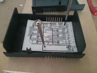
Testing the mounting hole fit with a cardboard print

What currently bugs me about this board is that due to the board layout, the channel sequence is kind of messed up. I'm not sure if I can still fix this on the board (I tried and failed two times already) or if I'll just stick with it and fix the channel sequence in software.

Also, before building this, I will need to find a source for PCA9685 chips, as they seem to be unavailable at my usual sources.