So you remember the bunch of boards I wired together for my previous post? Well, when I returned home today I was very happy to find a parcel full of electronic parts in the mail. It included the MAX3485 / MAX485 chips I ordered for this project, and with them I altered the circuit a little:
As you can see, most of the parts are still in place: bargraph display, PWM board, Arduino, Raspberry Pi. What you might be missing is the USB cable between the Pi and the Arduino: it's no longer necessary. Instead, the devices are now connected through a RS485 bus (the small, 3-wire cable that's visible between the Pi and the breadboard).
The amazing part is: In theory, when done right, that little cable can be extended to lengths of many meters, under certain conditions even kilometers. I don't think I will be going to such lengths, but that sure is enough to wire up a complete appartment or even house.
Another advantage of this concept is that I can daisy-chain multiple receivers to this bus, so that a single cable should be enough to wire up a whole lighting system.
This is very close to a DMX system already, however I think I will stick with the way it works now since I'm not sure wether the Raspberry Pi is capable of producing the necessary signal timing.
Some details.
Since the MAX3485 (a 3.3V compatible bus chip) was only available in an SMD package, I had to come up with a little testing shield in eagle:
This board is a mere transmitter due to the fact that the MAX3485 is designed for half-duplex mode. Switching between sending and receiving however would require an electronic signal that the Pi is (at least to my knowledge) unable to produce. I thought about wiring up a GPIO port, but this is purportedly too slow. Writing back to the Pi however is not really a requirement for my purpose, so I simply pulled the DE pin high, which means that this shield is only capable of transmitting data.
For the Arduino side, i wired everything onto a breadboard for now:
This is basically the same circuit, except that I used a MAX485 (the 5V equivalent) and pulled DE and RE low to put it into permanent receiving mode.
Next steps: I'm currently trying to figure out a protocol that will allow me to address multiple receivers on a single bus, without introducing too much of a delay. I'll post my results as soon as I worked something out.
Today I came up with another nice little contraption:
Now you're probably wondering what that is. That question is pretty easy to answer: From bottom to top, that's a Raspberry Pi driving an Arduino driving a PWM board driving a 10-LED-bargraph board.
Not satisfied with this answer? I can understand that. There's more questions behind that. Let's start with the less obvious things. Why the bargraph? It's a simple component that was readily assembled and was designed to be connected to the PWM board. It's a nice visual indicator of what's going on.
Why the PWM board? Again, the answer is: because I had one at hand. I could have used something else, but in combination with the bargraph again it gives a nice visual representation of what I was trying to accomplish.
So then the real deal is in the Arduino? From my previous projects I already know that I can directly interface the PWM board from the Pi. So basically there's not a real point in passing signals through an Arduino, or is there?
Yes there is. This is the first time I'm trying to build something Arduino-related at all, and this might actually turn out to be a nice advantage to future builds.
It's the connection between the Arduino and the Raspberry Pi that I will actually try to improve upon in the next days. So all this basically is going to be my testbed with a known-working state.
Right now I'm researching ways of replacing the connection with some kind of bus (RS485 seems very promising, and from there DMX is not far away) or even make it wireless (but most solutions appear to be rather expensive). If my idea works out, this could mean that I will no longer need a dedicated Pi for each of my devices, but instead a cheaper and smaller (think of the Mini!) Arduino would be sufficient. I might event manage to integrate the microcontroller directly onto my own boards!
And now this is an answer that hopefully gives you an insight on what really lies behind a few simple lights.
Oh, almost forgot, there's also a small video. Enjoy!
Well, so the 'ole traffic light I wrote about earlier has become a little obsolete recently, and so I wanted to give it a little overhaul. In my original post I already mentioned the four sides that it has, but since I was kind of lazy with the original build, only one side was actually connected. Also, since I kind of like the idea of integrating this into the PiLight system, I wanted to make the lights on it dimmable.
Since another project I'm currently working on will incorporate the PCA9685 chip, this is a good chance to try out a small part of the circuit before going large, and also makes the traffic light worthy of its own posts on this blog.
Here's a picture of the board I designed for this little project. It consists of a PCA9685, two ULN2803 amplifiers, a set of pre-resistors for the LEDs, and some more SMD passives for the configuration of the PCA.
Traffic light board design
I took some photos during the etching process for documentation. I'm working with the direct toner transfer method mainly because it's much more convenient (once you have access to a laser printer), but also because it requires less chemicals.
The first step is to cut out a piece of board that fits your dimensions.
Printed circuit on copper side (for illustration)
Marking the board dimensions on the board itself
Nice and shiny board after cutting
The next step is to transfer your design onto the actual board. This process involves a sheet of glossy paper (I just tore out a page of an old Reichelt catalogue, but from what I read most glossy magazines should do), some acetone, an iron, a bowl of soapy water and a brush.
Final board design printed onto glossy paper (had to glue it to a page of regular paper because it was too small)
Everything prepared: Iron, board, and the printout
Cleaning the board with acetone to remove any fingerprints or other kinds of dirt on the surface
Ironing the printout onto the board
This is what it looks like after ironing
Dumping the whole thing into a bowl of warm, soapy water
The paper will soak up completely in the water after a few minutes, and can then easily be brushed off.
This is what the board will look like after cleaning & drying.
I noticed at that point that the ground plane on the right side wasn't correctly transferred on. I would have been able to fix this by starting over, but since the plane in question was non-functional I didn't bother.
The board is now ready to be etched. (DISCLAIMER) Please note that the chemicals used in the following steps are dangerous and can seriously harm your health, clothes, workbench and the environment if used incorrectly. I will not take responsibility for any harm caused by you after reading this. (END OF DISCLAIMER)
The only thing that needs to be done now is to put the board into the etching solution of your choice. I'm using ferric chloride (Fe3Cl) basically because it was the only ethant available at our local electronics store. It works perfectly at room temperature, and will etch a board in typically twenty minutes.
Board submerged in etching solution
After about twenty minutes the board is usually ready to be washed off, the exact point of time however is best determined by repeated visual inspection of the etching process. Once all the non-printed areas are clear of copper, the board is finished.
This is what the board looks like after etching and cleaning:
To get the toner back off the board, simply use acetone:
After doing some quick measurements I noticed that some of the traces obviously were too close together, resulting in shorts between some of the leads. I had to cut them up using a utility knife:
Next step is to drill the holes for the through-hole components (I used a 0.8mm drill and a dremel for that):
Always put an old piece of wood under your board while drilling!
Finished!
That's all for now. I'm currently waiting for the components for the board to arrive (I finally found a source for the PCA9685, too) and will follow up with another post once they arrive.
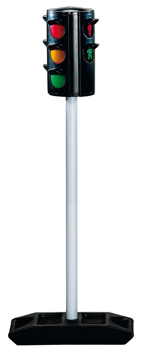
One of the first things I wanted to do with the Raspberry Pi was to turn one into an "extreme feedback device"1 because due to its size, the fact that it runs a fully-fledged Linux and the versatility of its connections it would be easy to interface both the server and some lights.
Because I wanted to start on the software early, I built a little mock-up device at first that did nothing more than connect three different color LEDs to GPIO pins on the Raspberry Pi:
I went with the "traffic light" color scheme because it matches the three different states used by Jenkins.
After wrapping up the code, I found the right hardware for this on Amazon:
I bought this since a life-size or real traffic light (yes, they are available on ebay every once in a while) would have been a little over the top price- and sizewise. It comes with two "car" sides (showing red, yellow and green) and two "pedestrian" sides (with only red and green). It has a switch with three positions on the bottom, and a pushbutton on the top. It originally runs off three AA batteries.
After opening it up I didn't really bother much with the original functionality and pretty much instantly ripped out the original board. What was unexpected though was the small tungsten light bulbs I found on the inside since I was really expecting LEDs. The good news at this point was that the removal of the original board freed enough space for a bare Raspberry Pi + WiFi to be fit inside.
After drilling up the holes and installing 5mm ultra-bright LEDs I hooked up another ULN2064 to amplify the GPIO outputs since the 30mA current necessary to drive the LEDs appeared a little bit too much for Raspberry Pi to me. I also drilled holes into the bottom and ran a power supply cable through the foot.
Here's a few pictures of it in action:
First experiments with regular LEDs that turned out to be too dark
1 An extreme feedback device is a tool often used in agile programming. Its purpose is to show the integrity of a software project. The idea is to detect software errors as soon as possible and to make them visible and obvious to everyone involved. It usually involves a continuous integration server like Jenkins.↩
I already wrote about the LED strips I connected to the Raspberry Pi in my previous post. In this post I would like to introduce a replacement I am currently working on for the PWM and amplifier boards.
I initially started this as a kind of "training" to get into CadSoft EAGLE (one of the standard programs out there to design your own PCBs) but as I worked this board over and over it seemed to actually fix a few of the issues I had with the old installation, and so my current plan is to actually build this and see how it works out.
This board also directly includes two PCA9685 chips to generate the PWM signal. I was reading a lot on how to control large amounts of LEDs and this chip turned up repeatedly. It was only then that I found out that I had already used this chip before: It is the core chip of the Adafruit 16-Channel PWM Servo board that was already part of my previous dimmer design.
And of course I stuck with the ULN2064 that has worked so well for me before.
Board improvements / features:
Channel count: The new dimmer would double the number of channels available to a total of 32 channels, while it should still fit into the same size case. There might even be enough space left inside the case to fit the Raspberry Pi inside, but I don't think it would be a good idea. The connectors on the Pi are placed on three different edges, thus not allowing me to expose them all.
Included power supply for the Raspberry Pi (the consumption of wall sockets has really become a pain lately)
Single board circuit (well, not exactly, I will need a separate board to stack the second row of outputs, but still that's only a fraction of the cables used in the previous revision)
Adressable: Only the lowest bit of the PCA9685 address is fixed by the board layout (due to the double-chip design). The other address bits can be set by solder jumpers.
Chainable: The board was designed with a second bus header, to allow chaining of multiple boards and / or other I2C devices.
Designed to fit the mounting holes inside a Euro Box (the casing I used before, easily available from many electronics distributors including Reichelt & Conrad)
I was able to fit the 4-pin Mini-DIN-connectors back onto the board again, so this should actually work as a drop-in replacement for the old dimmer.
This will probably be the first double-sided PCB I'm going to etch, and it also includes a bunch of SMD components, so I'm curious how it will turn out.
New board design
Testing the mounting hole fit with a cardboard print
What currently bugs me about this board is that due to the board layout, the channel sequence is kind of messed up. I'm not sure if I can still fix this on the board (I tried and failed two times already) or if I'll just stick with it and fix the channel sequence in software.
Also, before building this, I will need to find a source for PCA9685 chips, as they seem to be unavailable at my usual sources.
Fast forward to 2012, the year the first Raspberry Pi Model B computers hit the market. I got one pre-ordered very early, but still had to wait a couple of months for it to arrive. I can't remember exactly when it arrived, but I found first pictures in my collection to be dating back to October.
It must have been around that time that I found a 5 meter package of LED strips on sale at a local grocery store. It was one of those typical packages... 5m of RGB LED strip, cuttable, with connectors to go around corners, a power supply and a small but colorful infrared remote. I got one of these with the explicit intention to play around with it, so I was not that disappointed to find that the capabilities of the original package were kind of limited. I really wanted to hook this up to a computer, and what would be better suited for this than a Raspberry Pi?
And so I started fiddling again. This time I was not bound to DMX, so I figured my best choice would be one of Adafruit's PWM servo boards. I didn't intend to run servos from it, but since it was capable of outputting PWM at 5V i figured this would be enough to drive one of those ULN2064B chips I had already used before. The LED strips themselves turned out to be running at 12 volts once more, so this was all kind of a déjà-vu to me. The board also had a total of 16 output channels - enough to cut the strip into five pieces and control the red, green and blue values for each one individually.
First experiments looked promising:
Rasbperry Pi with PWM board driving four regular LEDs
So I hooked up a ULN2064 I still had from earlier work to the PWM board, used the power supply from the original package and things literally got brighter:
The video shows the complete setup: Raspberry Pi, PWM board, ULN2064 and LED strip.
After that, all I had to do was get a few more ULN2064s and a case to store the circuitry in.
Fitting the circuitry into a box
For connections to the outside, I used 4-pin Mini-DIN connectors, as they allowed me to bundle the necessary lines (one for red, green, blue and a V+ pin) into a single connector without using too much space.
Fitting the connectors
How it will once look when finished (lower case is still open)
Insides almost finished
One more inside shot
I ended up cutting the original strip into four pieces, because I found that a 4-pack of LED sticks I once purchased at IKEA also ran off 12V and worked perfectly with this new dimmer device, and so I used one output to power these.
Skip to today: After finally aquiring the materials needed to etch my own PCB boards, I am currently in the process of redesigning this dimmer. Click here for the follow-up post.
The first really notable LED-related project I did started back in the year 2009, when two friends came up to me and asked whether I could help them out with the sound & light of a local club they wanted to start. The venue was already known to me (as it has been a club location before), and for monetary reasons of course as much of the equipment still in place should be re-used.
One of the previous owners most notably had made a huge investment and had installed lots of led tubes into the club furniture, groups of red, green and blue, hidden behind acrylic glass. I had seen them in action (and even worked the old lighting system) before, but at that point had no idea how they were actually wired or controlled. Nevertheless, I agreed, and this picture best shows what I found:
Many projects start off with a certain level of messiness.
That's about 80 pieces of Halogen Transformers, 12V AC. The bunch of cables coming in at the top, that's the multicores going to the actual LEDs, and the lot of cables hanging out at the bottom... well, that's the remainder of the previous owner ripping out the 220V regular lighting dimmers that were previously used to power the whole system.
Now i won't go into all of the problems that this posed (the most important problem I'm gonna skip here is: which transformer powers which LED? Just let me say: we eventually figured it out...) but would like to focus onto the electronic problems that this setup posed:
Those transformers were AC units, meaning: no recifiers and no filters. That led to a constant flickering of the connected LEDs at 50Hz.
Lighting dimmers usually are designed for ohmic loads (which fits most regular lamps). Transformers are inductive loads and most available dimmers are only able to drive a fraction of their announced power for such types of loads.
LEDs cannot be dimmed by varying the applied voltage. The effect that regular voltage dimming has to LEDs is that they will be far too bright at lower dimming levels.
An 80-channel dimmer bank would have been pretty expensive. (We worked out that the original system obviously grouped the LEDs and only consisted of four dimmers with 6 channels each)
So, besides the fact that we set out to reconstruct the original system, I started lots and lots of research in order to improve upon what would initially work.
One of the very first things I learned was that the key to LED dimming is Pulse Width Modulation, or short: PWM. So whatever I was about to build needed to integrate into a club lighting environment (that means: would require a DMX input) and had to output a PWM signal at the required 12 Volts and would need to output enough power for some meters of LED tubing (measurements indicated up to 1.2 Gigawatts, err, I mean Ampere).
At that point I was lucky enough to find Hendrik Hoelscher's DMX board. It's a basic board driven by an Atmel ATmega8515 microcontroller that can be used for various lighting purposes, including LED dimming. The sample schematics showed an ULN2803 chip used for driving high-power LEDs, but the spec sheet showed that the maximum load of that chip was 500mA, which was not enough. After a bit of searching however i found the "big brother", the ULN2064, which (despite the limitation to four instead of 8 channels) was able to drive up to 1.5A. Awesome!
So I ordered a batch of the DMX boards, the necessary components, a few ULN2064 chips, grabbed a few leftover LED tubes, and put it all together.
Assembled DMX Transceiver board with virgin inputs & outputs
After programming the mictrocontroller initial testing was performed with regular LEDs and the internal standalone demo modes:
DMX Transceiver with regular LEDs connected directly
Next, the testing circuit was hooked up to an old DMX lighting controller (left over from one of the previous owners... we had no intentions using it again initally, but still it turned out quite useful later on):
DMX Transceiver connected to DMX lighting console
Since everything worked smoothly at that point, the next step was to hook up a sample ULN2064 to the transceiver, and attach a sample strip of LEDs. An old computer power supply was the only one that would provide enough power, so I hooked that up as a power source. I don't have pictures of that stage, only a short video:
This video also shows the software that we used to control it all, DMXControl, and a first sample effect I clicked together for a quick demonstration.
Now that the whole proof of concept stuff was successful, all I had to do was wrap it up into some kind of form we could really use. The DMX Board was able to drive nine individual outputs, and one ULN2064 could amplify four channels each. That lead to the final channel count of 36. The fact that we would be able to cover 72 channels with two these devices also was pretty convenient, since that pretty much matched the amount of LED tubes in place.
In addition to the 4 DMX boards I also soldered a long row of 72 terminals onto a strip of perfboard, which would hold the ULN2064s and a row of fuses, too.
Also, a PC power supply was not suitable for the final installation, so it was swapped out for a professional Mean Well 320W switching power supply that was able to drive a whopping 25 amps in total. This was the most expensive part of the installation.
Here's a few more pictures of the process:
Laying out the components: DMX boards on the left, terminal perfboard with ULN2064s still in packaging on the right, power supply on the bottom. Also shown: 9V AC transformer used to power the DMX boards
Putting things together for another test run
First completed dimmer in place with the first LEDs attached
Final installation: 2x36 channels, still some terminals available. I also started applying heat sinks to the amplifier chips for heat dissipation.
And to round it all up, here's another short video of the final LED dimmer in action:
Skipping to today, I don't work at that place any more. But as far as I know and was told my work is still in place and functioning.
What is this blog about? Well, right now, it is about nothing at all... But what it is supposed to be is some kind of a documentary about my personal little electronics projects.
Why is it called "PiLight"? Well, I started fiddling with those little credit-card sized computers called "Raspberry Pi" (let me tell you, they are awesome!) a while ago, and I found them to be extremely useful when it comes to controlling all sorts of LED lighting equipment. Since then I've been working on a lighting system called "pilight" to make all the little lights around my place to shine together in awesomeness. I'm not quite there yet, and here I wanted to write a little about my progress.
Who am I? My name's Jakob, I'm a big enthusiast when it comes to programming and computers in general, and electronics have always been a little hobby for me. Those recent experiences with the Pi have drawn me deeper into electronics, and I've only recently started designing and etching PCBs. This is a big step for me, and has opened up many new possibilities.
What's gonna be next? In the upcoming weeks I will try to cover some of the work that I've already done so far, and I'm also gonna by writing blog posts about what's currently on my table. So bear with me while this blog is developing.