Showing posts with label eagle. Show all posts

Thursday, February 12, 2015

The DMX Experience (Part 5 - the build)

So... since I did have to wait for my parts longer than expected this time (and I still wonder how that postal code got messed up on the parcel) and I couldn't really prepare anything ahead for this, it took me a little longer to finish.

After I finally got all the parts I needed and verified their board footprints (yes, those optocouplers are really that large, they seem like DIP-8 with cut leads) I etched and drilled the prototype board and started populating it. I started off with the microcontroller section so I could try to flash the firmware, but I was unlucky: I simply couldn't get the bare controller to show up in the USB device list. Thus, I was unable to flash any firmware over USB. Well, I'm happy I included the ISP header as a backup, because at least that one worked without a hitch.

While testing the DC-DC bridge I measured that the secondary power on my board was not really working as expected, and noticed that the IC was getting really hot. After some debugging I found out that I had accidentally reversed the polarity on the converter outputs. D'oh! The best I could think of was to unsolder the output pads and cross them over with some wires to properly power the circuit, which turned out to be an acceptable fix (at least for a prototype).

After populating the rest of the components, I hooked it up to my Raspberry Pi et voilá - it worked right away, at least the output (I'm still not done programming the input side).

So, with all that done, here's a little update on the Todo List of part 1:
  • Testing: Well, that is pretty much an ongoing task. My two LED PARs work perfectly, but that hardly counts as extensive testing.
  • PiLight Integration: Works perfectly as an output, but no work has been done on the input side.
  • DMX Input: no progress so far, except for the fact that the hardware has been included in the build.
  • Configuration: I can receive the configuration in the firmware by now, and I have started interpreting it with the AVR timer. Parameter storage to EPROM still needs to be done.
  • Galvanic isolation: Included and seems to work (at least I got rid of that nasty ground hum the first prototype had). I still need to evaluate if it really is effective against a few hundred to thousand volts.
  • Packaging: Well, I still need an enclosure :)
To round things up, here's a few pictures of the result:

Close-up view with LED PAR
Up and running with my new Raspberry Pi 2

Friday, January 30, 2015

The DMX Experience (Part 4 - new design)

I've spent the past few days designing a new PCB for the USB DMX interface. It's been an interesting experience working with Eagle again after some time, but after a few iterations and improvements I believe that I have found a pretty good design that fits all the hardware functions onto a rather compact form factor.

Current DMX board design

I've used A and B Series Neutrik XLR connectors that take up very little space, and I also managed to introduce galvanic isolation into the design (however I am not really sure whether or not the physical component spacing is sufficient to deflect an actual surge).

As you can see, the board incorporates an ICSP programming header; I included this for emergency use. The ATMega32u4 comes preprogrammed with a bootloader that allows flashing the firmware directly over USB. But since I don't have any experience with the process, I wanted to make sure that I can at least still test the rest of the circuit if problems come up.

Right now I'm waiting for all the parts to be delivered, so I can confirm the sizes of some of the components I had to build from scratch (are those optocouplers really that huge?).


Size testing the components.

Looks good, huh? If everything works out alright, I might finish this within the next week. Stay tuned!

Friday, September 6, 2013

Taking the bus (Part 2)

Over the last few days I've been working on a lot of small things, and I've had a lot of new interesting findings. This is a combined blogpost of all the new stuff I'm working on.

For one, I took apart my central pilight controller Raspberry (after a staggering uptime of 224 days!) and had it equipped with an upgraded version of the RS485 shield from my previous post. I didn't take pictures this time, but the RS485 part is basically still the same. What I've done is I've added both I2C and SPI outputs to the board for a directly attached LPD8806 strip and a 20*4 LCD display respectively.

From there, I ran a long network cable (about 10m) across my room for  RS485 testing. I would have preferred a phone line, but unfortunately I don't have one yet, and the network cable was the only cable at hand that met the electrical requirements and was long enough.

Pilight central command with attached RS485 line

On the other end of this line now sits an Arduino, which has already replaced the Raspberry Pi that was once used to drive the WS2801 LED pixel strand there.

I've been working on the serial protocol that is run over the RS485 line and the corresponding Arduino sketch to fix a few glitches. It's now operating properly, and will also allow me to address multiple target devices attached to a single line.

Also, a friend of mine that also happens to be the local Raspberry & Arduino dealer was so kind to provide me with a few more Arduino boards for experimenting, among them an Arduino Mini. I immediately had to try this one out, and after a little bit of fiddling with the cables (the Mini comes without USB, nor does it have a standard-compliant ISP port for programming) and modifying the sketches I was able to integrate it into my system successfully.

Arduino Mini with MAX485 on breadboard, RS485 line on the right

I also did a little measuring and was pleasantly surprised that the complete circuit on the breadboard consumes a mere 20mA. That (apart from other improvements like the drastically reduced latency) really is a huge advantage over the Raspberry Pi based solution.

Since all those little experiments have worked out so well, I've also had plenty of time to read up on where to go from here. I'm currently working on a first board that will in turn replace the Arduino again. I've taken the same microcontroller that sits on most Arduinos (the ATMEGA328P), added only the necessary components to make it work, a MAX485 bus driver and headers for ICSP, I2C and SPI. Here's what the design looks like:

Pilight universal controller board (size: 23*37mm)
It is slightly larger than the Arduino Mini (the TQFP package of the processor is bigger, and the Arduino does not have RS485) but it's still pretty tiny. I'm curious what case options will be available for such a small board.

I've also thought about a way to get some configuration (like device ids) onto the controllers (that's what the CONFIG jumper is for) but I haven't had the time to test it out yet, so this will be part of a later post.

I've also postponed the production of the new LED dimmer for now, since the current version is designed to be driven by an external controller (in my original plan that would have been a Raspberry Pi). With all those new findings however I'd really like to integrate the controller right into the dimmer itself, which would allow me to directly connect it to the RS485 bus without any additional hardware.

Next steps will be to compile a list of parts for the new controller, since this will most probably be the next device for me to build. I'll post another update on this soon.

Wednesday, August 28, 2013

The new traffic light

Well, so the 'ole traffic light I wrote about earlier has become a little obsolete recently, and so I wanted to give it a little overhaul. In my original post I already mentioned the four sides that it has, but since I was kind of lazy with the original build, only one side was actually connected. Also, since I kind of like the idea of integrating this into the PiLight system, I wanted to make the lights on it dimmable.

Since another project I'm currently working on will incorporate the PCA9685 chip, this is a good chance to try out a small part of the circuit before going large, and also makes the traffic light worthy of its own posts on this blog.

Here's a picture of the board I designed for this little project. It consists of a PCA9685, two ULN2803 amplifiers, a set of pre-resistors for the LEDs, and some more SMD passives for the configuration of the PCA.

Traffic light board design
I took some photos during the etching process for documentation. I'm working with the direct toner transfer method mainly because it's much more convenient (once you have access to a laser printer), but also because it requires less chemicals.

The first step is to cut out a piece of board that fits your dimensions.

Printed circuit on copper side (for illustration)

Marking the board dimensions on the board itself

Nice and shiny board after cutting
The next step is to transfer your design onto the actual board. This process involves a sheet of glossy paper (I just tore out a page of an old Reichelt catalogue, but from what I read most glossy magazines should do), some acetone, an iron, a bowl of soapy water and a brush.

Final board design printed onto glossy paper (had to glue it to a page of regular paper because it was too small)

Everything prepared: Iron, board, and the printout

Cleaning the board with acetone to remove any fingerprints or other kinds of dirt on the surface

Ironing the printout onto the board

This is what it looks like after ironing

Dumping the whole thing into a bowl of warm, soapy water

The paper will soak up completely in the water after a few minutes, and can then easily be brushed off.

This is what the board will look like after cleaning & drying.
I noticed at that point that the ground plane on the right side wasn't correctly transferred on. I would have been able to fix this by starting over, but since the plane in question was non-functional I didn't bother.

The board is now ready to be etched. (DISCLAIMER) Please note that the chemicals used in the following steps are dangerous and can seriously harm your health, clothes, workbench and the environment if used incorrectly. I will not take responsibility for any harm caused by you after reading this. (END OF DISCLAIMER)

The only thing that needs to be done now is to put the board into the etching solution of your choice. I'm using ferric chloride (Fe3Cl) basically because it was the only ethant available at our local electronics store. It works perfectly at room temperature, and will etch a board in typically twenty minutes.

Board submerged in etching solution
After about twenty minutes the board is usually ready to be washed off, the exact point of time however is best determined by repeated visual inspection of the etching process. Once all the non-printed areas are clear of copper, the board is finished.

This is what the board looks like after etching and cleaning:


To get the toner back off the board, simply use acetone:


After doing some quick measurements I noticed that some of the traces obviously were too close together, resulting in shorts between some of the leads. I had to cut them up using a utility knife:


Next step is to drill the holes for the through-hole components (I used a 0.8mm drill and a dremel for that):

Always put an old piece of wood under your board while drilling!

Finished!
That's all for now. I'm currently waiting for the components for the board to arrive (I finally found a source for the PCA9685, too) and will follow up with another post once they arrive.

Monday, August 26, 2013

The new LED dimmer

I already wrote about the LED strips I connected to the Raspberry Pi in my previous post. In this post I would like to introduce a replacement I am currently working on for the PWM and amplifier boards.

I initially started this as a kind of "training" to get into CadSoft EAGLE (one of the standard programs out there to design your own PCBs) but as I worked this board over and over it seemed to actually fix a few of the issues I had with the old installation, and so my current plan is to actually build this and see how it works out.

This board also directly includes two PCA9685 chips to generate the PWM signal. I was reading a lot on how to control large amounts of LEDs and this chip turned up repeatedly. It was only then that I found out that I had already used this chip before: It is the core chip of the Adafruit 16-Channel PWM Servo board that was already part of my previous dimmer design.

And of course I stuck with the ULN2064 that has worked so well for me before.

Board improvements / features:
  • Channel count: The new dimmer would double the number of channels available to a total of 32 channels, while it should still fit into the same size case. There might even be enough space left inside the case to fit the Raspberry Pi inside, but I don't think it would be a good idea. The connectors on the Pi are placed on three different edges, thus not allowing me to expose them all.
  • Included power supply for the Raspberry Pi (the consumption of wall sockets has really become a pain lately)
  • Single board circuit (well, not exactly, I will need a separate board to stack the second row of outputs, but still that's only a fraction of the cables used in the previous revision)
  • Adressable: Only the lowest bit of the PCA9685 address is fixed by the board layout (due to the double-chip design). The other address bits can be set by solder jumpers.
  • Chainable: The board was designed with a second bus header, to allow chaining of multiple boards and / or other I2C devices.
  • Designed to fit the mounting holes inside a Euro Box (the casing I used before, easily available from many electronics distributors including Reichelt & Conrad)
  • I was able to fit the 4-pin Mini-DIN-connectors back onto the board again, so this should actually work as a drop-in replacement for the old dimmer.
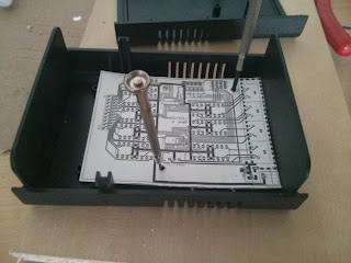
This will probably be the first double-sided PCB I'm going to etch, and it also includes a bunch of SMD components, so I'm curious how it will turn out.

New board design
Testing the mounting hole fit with a cardboard print

What currently bugs me about this board is that due to the board layout, the channel sequence is kind of messed up. I'm not sure if I can still fix this on the board (I tried and failed two times already) or if I'll just stick with it and fix the channel sequence in software.

Also, before building this, I will need to find a source for PCA9685 chips, as they seem to be unavailable at my usual sources.