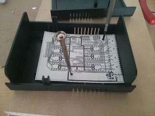
I initially started this as a kind of "training" to get into CadSoft EAGLE (one of the standard programs out there to design your own PCBs) but as I worked this board over and over it seemed to actually fix a few of the issues I had with the old installation, and so my current plan is to actually build this and see how it works out.
This board also directly includes two PCA9685 chips to generate the PWM signal. I was reading a lot on how to control large amounts of LEDs and this chip turned up repeatedly. It was only then that I found out that I had already used this chip before: It is the core chip of the Adafruit 16-Channel PWM Servo board that was already part of my previous dimmer design.
And of course I stuck with the ULN2064 that has worked so well for me before.
And of course I stuck with the ULN2064 that has worked so well for me before.
Board improvements / features:
- Channel count: The new dimmer would double the number of channels available to a total of 32 channels, while it should still fit into the same size case. There might even be enough space left inside the case to fit the Raspberry Pi inside, but I don't think it would be a good idea. The connectors on the Pi are placed on three different edges, thus not allowing me to expose them all.
- Included power supply for the Raspberry Pi (the consumption of wall sockets has really become a pain lately)
- Single board circuit (well, not exactly, I will need a separate board to stack the second row of outputs, but still that's only a fraction of the cables used in the previous revision)
- Adressable: Only the lowest bit of the PCA9685 address is fixed by the board layout (due to the double-chip design). The other address bits can be set by solder jumpers.
- Chainable: The board was designed with a second bus header, to allow chaining of multiple boards and / or other I2C devices.
- Designed to fit the mounting holes inside a Euro Box (the casing I used before, easily available from many electronics distributors including Reichelt & Conrad)
- I was able to fit the 4-pin Mini-DIN-connectors back onto the board again, so this should actually work as a drop-in replacement for the old dimmer.
This will probably be the first double-sided PCB I'm going to etch, and it also includes a bunch of SMD components, so I'm curious how it will turn out.
What currently bugs me about this board is that due to the board layout, the channel sequence is kind of messed up. I'm not sure if I can still fix this on the board (I tried and failed two times already) or if I'll just stick with it and fix the channel sequence in software.
Also, before building this, I will need to find a source for PCA9685 chips, as they seem to be unavailable at my usual sources.
 |
| New board design |
 |
| Testing the mounting hole fit with a cardboard print |
What currently bugs me about this board is that due to the board layout, the channel sequence is kind of messed up. I'm not sure if I can still fix this on the board (I tried and failed two times already) or if I'll just stick with it and fix the channel sequence in software.
Also, before building this, I will need to find a source for PCA9685 chips, as they seem to be unavailable at my usual sources.
No comments:
Post a Comment